Of course, you can buy a GPS receiver in China for a few dollars. Or you may not buy it - you still have it in your phone, in the navigator in your car ... But if you want to be a real hacker-engineer and understand GPS technology at a low level, then welcome to this article. Let's figure it out so that it won't seem a little!This article was written for educational purposes only. We do not call anyone to anything, only for information purposes! The author is not responsible for your actions
The history of the development of the Global Positioning System (GPS) dates back to the 50s of the last century, and the first satellite was launched in 1974. Initially, the system was used only by the military, but after the tragedy with the Korean Airlines plane, which was shot down over the territory of the USSR, civil services also got the opportunity to work with GPS. In 1993, it was finally decided to provide GPS for use by civil services at no cost, and after disabling the intentional rounding of the position, the accuracy increased from one hundred meters to twenty. These days, accuracy continues to improve and the cost of receivers continues to decline. Therefore, anyone who was born with a soldering iron instead of ... okay, okay, it was a joke, can make a GPS logger, or a navigator. One does not exclude the other
") .
.Materiel
So what is our device supposed to do?
- Get information about the current position from the GPS receiver.
- Disassemble it.
- Show on the screen the current position of the receiver, as well as visible satellites.
GPS
Of course, it is not necessary to understand in detail the nuances of GPS operation, since all the work on calculating coordinates, speed, course and other parameters will be taken over by the GPS receiver. But you need to know the base.
First of all, you need to understand that a GPS receiver never transmits anything to satellites (if you don't believe me, just pay attention that receivers can be the size of a USB flash drive, while the antennas of satellite phones are sometimes larger than the phone itself). The task of satellite navigation is to determine its coordinates by the receiver, if the exact coordinates of the transmitters are known. If we know the distance to the satellites, then using elementary geometric constructions, we can calculate our coordinates with some accuracy.
To find the distance between the receiver and the transmitter, you must first synchronize their clocks, and then calculate the desired distance, knowing the speed of propagation of the radio wave, as well as the delay between the time of transmission and the time of reception ...
As I wrote above, the receiver needs to know the exact positions of the transmitters. This information is provided by the transmitter and is called an "almanac". Naturally, this information becomes outdated, therefore, depending on the "freshness" of the almanac, three types of delay can be distinguished between turning on the receiver and determining its first exact coordinates: "cold start", "warm start" and "hot start".
There are ways that can reduce the start time: AGPS (receiving the almanac by alternative means - via the Internet or by Russian Post), DGPS (eliminating signal distortion by the atmosphere) and others. But I will not consider them, since this is not necessary to accomplish the task at hand.
Now let's figure out in what form the calculated coordinates appear at the output of the device. There is a special standard for this.
NMEA-0183
NMEA stands for National Marine Electronics Association, and NMEA-0183 (according to Wikipedia) is a textual protocol for communication of marine (usually navigation) equipment (or equipment used in trains) with each other. Here are the lines coming from my receiver.
Code:
(...)
$GPRMC,174214.00,A,5541.23512,N,03749.12634,E,3.845,178.09,150914,,,A*6F
$GPVTG,178.09,T,,M,3.845,N,7.121,K,A*35
$GPGGA,174214.00,5541.23512,N,03749.12634,E,1,04,4.98,178.2,M,13.1,M,,*56
$GPGSA,A,3,20,14,04,17,,,,,,,,,8.85,4.98,7.31*02
$GPGSV,4,1,16,01,67,242,,02,,,15,03,,,15,04,53,284,35*74
$GPGSV,4,2,16,05,,,23,07,,,19,08,,,21,10,,,24*7F
$GPGSV,4,3,16,11,,,14,12,,,12,14,35,058,37,17,24,311,34*72
$GPGSV,4,4,16,20,40,275,29,22,08,097,,37,25,199,27,39,25,195,32*73
$GPGLL,5541.23512,N,03749.12634,E,174214.00,A,A*6D
(...)
First, let's define the similar parts of each line. It is easy to see that they all begin the same way and end more or less the same way. $GP - the information comes from the GPS receiver (you understand that there are a bunch of other sensors on the ship: if we had an emergency beacon, then the line would start with $EP, and if the echo sounder, then with $SD, and so on) ... Each line must end with the XOR checksum of all bytes in the line starting from $ and ending * - these are exactly the two characters at the end of the line. And do not forget about the characters <CR> and <LF> after checksum. Let's take a closer look at each of the lines.
$GPRMC,hhmmss.ss,A,aaaa.aaaa,N,bbbb.bbbb,E,c.c,d.d,DDMMYY,z1,z2,e*ff
- GPRMC - GPS Recommended Minimum Navigation Information sentence C - Recommended minimum navigation information, string type C.
- hhmmss.ss - the time according to universal time UTC, when the position was fixed.
- A - information reliability flag. If V, then the information cannot be trusted.
- aaaa.aaaaa - the value of latitude. The first two digits are degrees, the second two are the integer value of the number of arc minutes, after the dot - the fractional part of the number of arc minutes (variable length).
- N - northern latitude. If S, then the southern one.
- bbbb.bbbbb - the value of longitude. The first two digits are degrees, the second two are the integer value of the number of arc minutes, after the dot - the fractional part of the number of arc minutes (variable length).
- E - Eastern longitude. If W, then the western one.
- c.c - horizontal speed in knots (multiply by 1.852 to get speed in kilometers per hour), whole and fractional parts have variable length.
- d.d - direction of speed (track angle, course) in degrees, integer and fractional parts have variable length.
- DDMMYY - The current date.
- z1 - the value of the direction of magnetic declination that we do not have.
- z2 - also the direction of magnetic declination that is missing from us.
- e - mode indicator.
- ff - check sum.
$GPVTG,a.a,T,b.b,M,c.c,N,d.d,K,A*e
- $GPVTG - GPS Track Made Good and Ground Speed - line with information about course and speed.
- a.a - course in degrees.
- T - True, information validity flag.
- b.b - the direction of magnetic declination (we don't have it).
- M - Magnetic, yes, really magnetic.
- c.c - horizontal speed in knots (multiply by 1.852 to get speed in kilometers per hour).
- N - kNots, nodes.
- d.d - horizontal speed in kilometers per hour (and nothing needs to be multiplied).
- K - kilometers per hour.
- ee - check sum.
$GPGGA,hhmmss.ss,a.a,N,b.b,E,c,d,e.e,f.f,M,g.g,M,h.h,*i
- $GPGGA - Global Positioning System Fix Data - a line with information about the current location.
- hhmmss.ss - the time according to universal time UTC, when the position was fixed.
- a.a - the value of latitude.
- N - northern latitude. If S, then the southern one.
- b.b - the value of longitude.
- E - Eastern longitude. If W, then the western one.
- c - flag of the GPS signal quality.
- d - the number of satellites used.
- e.e - Dilution of precision (DOP) factor.
- f.f - the height of the receiver above sea level.
- M - the height is given in meters.
- g.g - the difference between a geoid (the true shape of our planet) and an ellipsoid according to WGS84 (a three-dimensional coordinate system for positioning).
- M - the difference is given in meters.
- h.h - number of the station transmitting DGPS corrections.
- i - check sum.
$GPGSA,A,x,y1,y2,y3,y4,y5,y6,y7,y8,y9,y10,y11,y12,z1,z2,z3*i
- $GPGSA - GPS DOP and Active satellites - a line with information about the satellites used to determine the location and the factors of decrease in accuracy.
- A - automatic mode of selection of work in 2D or 3D, M - manual mode, when rigidly selected, for example, 2D.
- x - receiver operating mode: 0 - coordinates are not determined, 1 - 2D mode, 2 - 3D mode.
- y1..y12 - the numbers of the satellites used to locate the receiver.
- z1..z2 - PDOP, HDOP, VDOP (factors of reduction of accuracy in position, in the horizontal plane and in the vertical plane, respectively).
- i - check sum.
$GPGSV,a,b,c1,d1,e1,f1,c2,d2,e2,f2,c3,d3,e3,f3,c4,d4,e4,f4*i
- GPGSV - GPS Satellites in View - the line contains information about the number, azimuth, altitude and signal-to-noise ratio of the satellite. There can be a maximum of four satellites in a row.
- a - the total number of lines GPGSV.
- b - current line number.
- c1..c4 - satellite number.
- d1..d4 - height above the horizon in degrees (0..90).
- e1..e4 - the azimuth of the satellite in degrees (0..359).
- f1..f4 - signal-to-noise ratio in dB (0..99).
$GPGLL,5541.23512,N,03749.12634,E,174214.00,A,A*6D - it makes no sense to dwell on this line in detail, since it contains coordinates and time, and we already have this in lines GPRMC and GPGGA.
Of course, manufacturers of GPS receivers are not prohibited from adding their own strings. On my receiver, you can see the following at startup:
Code:
$GPTXT,01,01,02,u-blox ag - www.u-blox.com*50
$GPTXT,01,01,02,HW  UBX-G60xx  00040007 FF7FFFFFp*53
$GPTXT,01,01,02,ROM CORE 7.03 (45969) Mar 17 2011 16:18:34*59
$GPTXT,01,01,02,ANTSUPERV=AC SD PDoS SR*20
$GPTXT,01,01,02,ANTSTATUS=DONTKNOW*33
$GPTXT,01,01,02,ANTSTATUS=INIT*25
$GPTXT,01,01,02,ANTSTATUS=OK*3B
Bresenham's algorithm
This algorithm is one of the oldest computer graphics algorithms - it was developed by Jack Bresenham (IBM) back in 1962. With its help, the graphic primitive is rasterized, in other words, this algorithm determines the coordinates of the pixels that must be lit on the screen so that the resulting drawing of the primitive coincides with the original.
Imagine that we are drawing a line from point (0; 0) to (100, 32), as you remember, our screen has a resolution of 128 x 64 pixels. It is easy to calculate that the angle between this line and the X-axis is less than 45 degrees. The operation of the algorithm consists in sequentially enumerating all coordinates along the X axis in the range from 0 to 100 and calculating the corresponding Y coordinate. It is logical that in most cases the value of the Y coordinate will be fractional, which means that you need to somehow select an integer coordinate value. This is done by selecting the closest pixel. For other angles of inclination of a straight line, as well as for circles, ellipses and other things, the algorithm has a similar form (you can read more about it on Wikipedia).
Bresenham's algorithm only uses integer addition and subtraction operations: usually using fractional arithmetic slows down the controller. Usually, but not in our case, since inside the STM32F303VC controller there is an ARM Cortex-M4 core with FPU. FPU (Floating Point Unit) is a device that accelerates work with fractional numbers (mathematical coprocessor), so nothing limits us and we can use the DDA line algorithm. An interesting demonstration of MK acceleration when drawing fractals can be viewed on YouTube.
Iron
What are we using in the project?
- Debug board STM32F3-Discovery;
- UART GPS NEO-6M module from WaveShare based on u-blox NEO-6M receiver;
- LCD matrix MT-12864A.
I talked about the LCD screen in the September issue (No. 188), briefly I will only say that it is made on the basis of the KS0108 controllers, and the connection diagram to the STM32F3-Discovery has not changed: the connector for connecting the screen contains 20 pins, the description is presented in the list by the following mask: <number> - <name from datasheet> - <description from datasheet> - <where to connect>.
- 1 - Ucc - Power - to 5V on Discovery.
- 2 - GND - Ground - to GND on Discovery.
- 3 - Uo - LCD panel power input for contrast control - to a trimmer.
- 4..11 - DB0..DB7 - data bus - to PD0..PD7 on Discovery.
- 12, 13 - E1, E2 - controller selection - to PD8, PD9 on Discovery.
- 14 - RES - reset - to PD10 on Discovery.
- 15 - R / W - select: read / write - to PD11 on Discovery.
- 16 - A0 - select: command / data - to PD12 on Discovery.
- 17 - E - data strobing - to PD13 on Discovery.
- 18 - Uee - DC-DC converter output - to a trimming resistor.
NEO-6M
This receiver is manufactured by the Swiss company u-blox, founded in 1997. The Neo-6 line of modules is represented by G, Q, M, P, V and T versions, each of which has its own characteristic capabilities: for example , the Neo-6P has the ability to very accurately (with an error of <1 m) position determination due to the Precise Point method Positioning (PPP).
The Neo-6M receiver has the following features:
- cold or warm start time - 27 s;
- hot start time - 21 s;
- maximum frequency of information output - 1 Hz;
- pulse frequency range per PPS pin - 0.25 Hz - 1 kHz;
- maximum position determination accuracy - 2.5 m;
- maximum speed determination accuracy - 0.1 m / s;
- the maximum accuracy of determining the course is 0.5 degrees.
To work with receivers, there is the original u-center utility, which at the time of this writing is version 8.11 (Fig. 1).
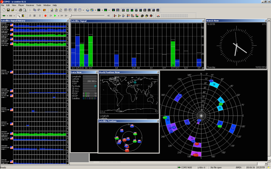
Rice. 1. General view of u-center
It can be seen that the Neo-6M has enormous potential, but there will not be enough space to describe all its capabilities in detail, so we will limit ourselves to those offered out of the box: only UART at 9600, only NMEA, pulse frequency - 1 Hz.
In terms of connection, everything is extremely simple: the VCC, GND, RX and TX lines on the receiver are connected to + 3.3V, GND, PA9 and PA10 on Discovery, respectively.
Program
It should display the current position of the receiver, speed, direction of movement, factors of decrease in accuracy, time, date, and also show the satellites used in the polar coordinate system. This is roughly how u-center does it in Fig. 2.
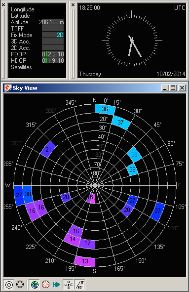
Rice. 2. Waiting for what will be shown on the screen 128 x 64
As soon as the string line from Neo-6M is received by the controller, it is split into tokens (array charTokens) - into substrings, which are separated by commas in the original string.
Code:
char * token = malloc (strlen (line) + 1);
char * token2 = malloc (strlen (line) + 1);
int currentTokenNumber = 0;
int currentCharInTokenNumber = 0;
strcpy (token, line);
char * delimeter = ",";
while (token! = NULL) {
   token2 = strpbrk (token + 1, delimeter);
   if (token2 == NULL) {
     // At the end of the line, change the separator to "*"
     delimeter = "*";
     token2 = strpbrk (token + 1, "*");
   }
   / * Copy part of the line between delimiters * /
   currentCharInTokenNumber = 0;
   / * Clear the token value * /
   memset (charTokens [currentTokenNumber], '', MAX_TOKEN_LENGTH);
   for (char * ch = token + 1; ch <token2; * (ch ++)) {
     charTokens [currentTokenNumber] [currentCharInTokenNumber] = * ch;
     currentCharInTokenNumber ++;
   }
   currentTokenNumber ++;
   if (delimeter [0] == '*') {
     token = NULL;
   } else {
     token = token2;
   }
}
It would seem quite logical to use a function strtok, but I don't. I'll show you the reason with an example. Let there be a string a,b,,,c. Of result of breaking Of Of Of Of of of of of of of of of IT of The Into tokens to to to to Via strtok is: 'a', 'b', 'c'. This is unacceptable for parsing NMEA, since in this protocol the token values depend on the position in the string. The result of the method described above includes empty tokens - 'a', 'b', '0', '0' 'c'.
For convenient storage of information about the position of the receiver, about the accuracy of determining the position, as well as about the parameters of the satellites, three data structures were written.
Receiver position and speed, as well as date and time:
Code:
struct _minimumNavigationInfo {
  float latitude;
  char latModificator; // East or West
  float longitude;
  char lonModificator; // North or South
  float groundSpeed;
  float speedAngle;
  float height;
  char heightModificator; // Metres or smth else
  char time[9]; // "hh:mm:ss"
  char date[9]; // "DD.MM.YY"
  char isValid;
};
Coordinate determination accuracy structure:
Code:
struct _fixInfo {
  double PDOP;
  double HDOP;
  double VDOP;
};
Structure about the satellite number, its position and signal quality:
Code:
struct _satelliteInfo {
  int satelliteId;
  float height;
  float azimuth;
  float SNR; //signal-to-noise ratio -- соотношение сигнал/шум
  int isFull;
};
If the information about the satellite is not complete, for example, there is information about the altitude and azimuth, but not about the signal-to-noise ratio, then a isFull zero value is written in the field. Such satellites will be ignored when displayed on the "radar".
Filling a structure based on an array of tokens is very simple: after parsing the string GPGSA in the array, the charTokens values of the precision reduction factors * DOP are in elements numbered 15, 16, and 17.
Code:
fixInfo->PDOP = atof(charTokens[15]);
fixInfo->HDOP = atof(charTokens[16]);
fixInfo->VDOP = atof(charTokens[17]);
Now you can safely display the parsed information on the screen (Fig. 3).
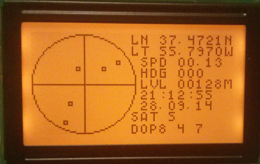
Rice. 3. Here comes the reality!
FIN
Now you know that there is nothing difficult in GPS either (if you do not go into the jungle), and if you want to understand the essence of satellite navigation, then welcome to the course from Stanford GPS: An Introduction to Satellite Navigation, with an interactive Worldwide Laboratory using Smartphones or from the University of Minnesota From GPS and Google Maps to Spatial Computing on Coursera.
And as a homework assignment, I will give you three tasks:
1. Add the ability to record a track.
2. Replace the monochrome screen with a color one.
3. Together with WizFi220 (from room 188), equip the device with the ability to receive A-GPS.
xakep.ru